Description:
Basics of Engineering Drawing is a fundamental skill in the world of design and manufacturing. The basic knowledge required in engineering drawing, including essential concepts, types of views, and common tools used. Discover how this technical skill forms the backbone of accurate, effective communication in engineering.
What is Basics of Engineering Drawing?
Basics of Engineering Drawing is a specialized form of technical drawing used to communicate ideas, specifications, and instructions for manufacturing or construction projects. It’s the visual language of engineers and designers, allowing them to share precise details and ensure that projects are built exactly as intended. Whether you’re designing a bridge, a piece of machinery, or a small component, engineering drawing is crucial for conveying every aspect of your design.
To understand engineering drawing, it’s essential to grasp some core concepts, from the types of views to the standards and tools used in creating accurate and clear drawings.
Why Basics of Engineering Drawing Matters
In engineering, a small mistake can lead to significant issues in production, efficiency, and safety. Engineering drawings provide a standardized way of sharing information across teams and professionals, reducing miscommunication. These drawings are used in various fields like mechanical engineering, civil engineering, electrical engineering, and architecture. By ensuring that each line and symbol is precise, engineers can make informed decisions, work more effectively, and meet quality standards.

Core Concepts in Basics of Engineering Drawing
1. Lines and Their Meanings
Different types of lines have unique meanings in engineering drawings:
- Continuous Lines: Represent visible edges and outlines of objects.
- Dashed Lines: Show hidden features that are not visible in the specific view.
- Center Lines: Indicate the center of objects or symmetrical parts.
- Dimension Lines and Extension Lines: Used to define the size and placement of features on an object.
Understanding the use and significance of each line type helps ensure clarity and avoid confusion in interpreting the drawing.
2. Types of Views in Basics of Engineering Drawing
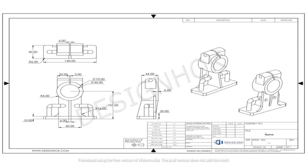
Engineering drawings commonly include different views to represent an object in full detail. The main views are:
- Front View: Shows the object as seen from the front.
- Top View: Offers a view from above, providing a different angle of the design.
- Side View: Displays the object from the side, showing depth and other key details.
- Isometric View: A 3D representation that combines multiple angles for a more realistic perspective.
Using these views, engineers can communicate all the details of a complex object without ambiguity.
3. Dimensions and Tolerances
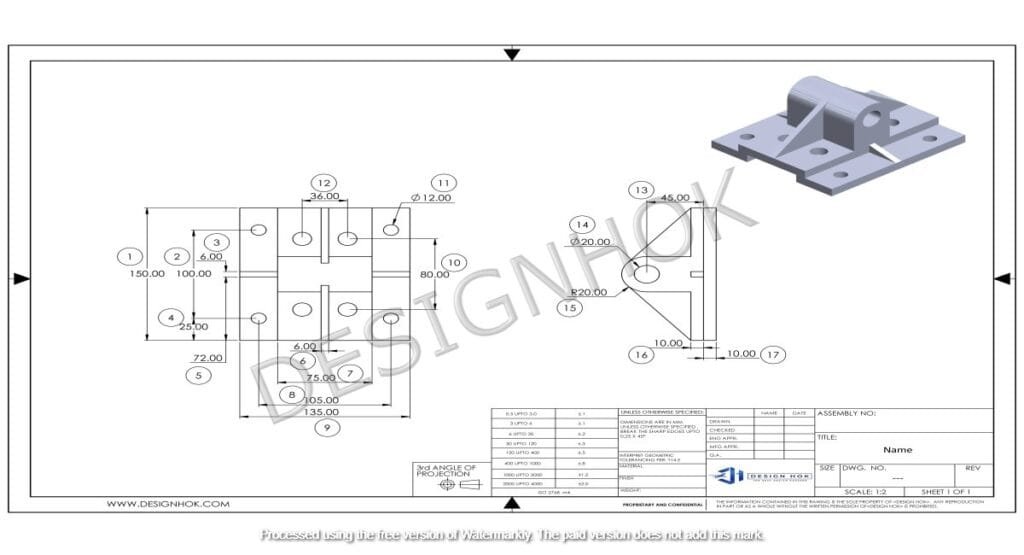
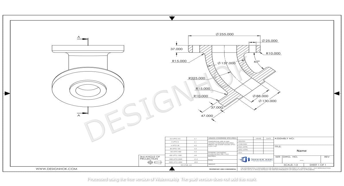
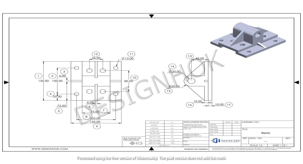
Dimensions are critical as they specify the size of each element in the design, such as height, width, and depth. Tolerances are equally important; they define the acceptable range of variation in the size of parts. By clearly marking dimensions and tolerances, engineers ensure that components fit together precisely and function as intended.
4. Scale
Engineering drawings are usually drawn to scale, meaning they represent the object at a reduced or enlarged size while maintaining proportions. Common scales are 1:1 for life-size, 1:2 for half-size, or 2:1 for double-size. Using the correct scale helps professionals understand the actual size of the design and fit it within the larger project.
5. Symbols and Notations
Symbols in engineering drawing represent various elements, such as materials, surface finishes, and geometric shapes. These symbols make it easier to read and interpret the drawing. For example, weld symbols indicate the type of welding required, while material symbols specify the material type, such as steel or plastic.
6. Projection Methods
Projection methods are techniques for representing a 3D object on a 2D plane. The two main types are:
- First-Angle Projection: Common in Europe and Asia, it shows the object’s front view on the left and the side view on the right.
- Third-Angle Projection: Used mainly in the United States, where the front view is placed in the center, and other views are arranged accordingly.
Understanding these methods ensures that drawings are interpreted correctly across regions and disciplines.

Essential Tools in Basics of Engineering Drawing
Creating engineering drawings requires several basic tools, from traditional to digital:
- Compass and Protractor: For creating circles and measuring angles.
- Ruler and Scale: To ensure accurate measurements.
- Drafting Table: Provides a stable surface to create precise drawings.
- CAD Software: Computer-Aided Design (CAD) tools like AutoCAD and SolidWorks have become essential in modern engineering drawing. They enable quick revisions, accurate scaling, and complex 3D modeling, which traditional tools cannot achieve.
Standards in Basics of Engineering Drawing
To ensure consistency and clarity, engineering drawings follow specific standards. These standards include:
- ISO (International Organization for Standardization): Establishes global standards for engineering drawings, covering everything from line types to symbols.
- ASME (American Society of Mechanical Engineers): Defines standards for mechanical engineering drawings used widely in the U.S.
- BS (British Standards): Used in the U.K., especially for civil and architectural drawings.
Adhering to these standards ensures that drawings are universally understood, regardless of geographic location or industry.
How to Interpret an Basics of Engineering Drawing
Reading an Basics of Engineering Drawing takes practice and a strong understanding of the symbols, lines, and views used. Here are a few steps:
- Identify the Views: Determine which views are provided—front, top, side, or isometric.
- Understand Dimensions and Tolerances: Review all dimensions to understand the size and acceptable limits of each component.
- Examine Symbols and Notations: Look at symbols to interpret specific requirements, like materials and surface finishes.
- Check the Scale: Confirm the scale to understand the object’s actual size relative to its representation in the drawing.
By systematically reviewing each part of the drawing, engineers can accurately interpret and execute the design.
Conclusion
Basics of Engineering Drawing is an essential skill for engineers across various fields, serving as the main tool for conveying technical information and design details. From understanding line types and views to interpreting symbols and following standards, mastering these basics is critical for anyone involved in design, manufacturing, or construction. With the rise of CAD software, engineering drawing has become more efficient and precise, further highlighting its importance in modern engineering.
Frequently Asked Questions (FAQs)
1. Why is engineering drawing important? Engineering drawing is essential for sharing design information accurately, allowing engineers and manufacturers to understand project specifications clearly.
2. What are the main views in an engineering drawing? The main views are the front, top, side, and isometric views, each offering a unique angle for a full understanding of the design.
3. What is the purpose of dimensioning in engineering drawing? Dimensioning specifies the exact size and placement of parts, ensuring each component fits together correctly.
4. How do projection methods affect engineering drawings? Projection methods, like first-angle and third-angle, determine how views are arranged, affecting how the drawing is read and interpreted.
5. What tools are used in engineering drawing today? Traditional tools like rulers and compasses are still used, but CAD software, like AutoCAD and SolidWorks, has become standard for creating precise and modifiable drawings.


