
Description:
Explore how DesignHok leverages machine component visualization to enhance design accuracy, streamline workflows, and empower innovation in mechanical engineering. Discover its role, tools used, benefits, and why it’s a game-changer for modern manufacturing.
In the ever-evolving world of mechanical engineering, the ability to visualize machine components before they are manufactured is not just a luxury—it’s a necessity. At DesignHok, we believe that machine component visualization is the cornerstone of successful product development. By creating accurate digital representations of mechanical parts, engineers and designers can identify flaws, ensure compatibility, and enhance efficiency across the entire product lifecycle.
In this blog, we will explore what machine component visualization means, how it’s used at DesignHok, the tools we rely on, and the numerous benefits it offers to clients across industries.
What is Machine Component Visualization?
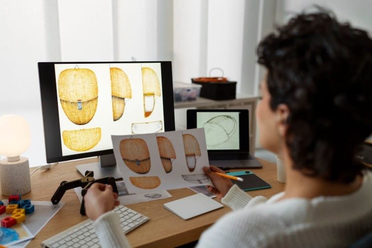
Machine component visualization is the process of creating detailed visual representations of individual mechanical parts or assemblies using 2D or 3D CAD (Computer-Aided Design) tools. These visualizations can include dimensions, materials, surface finishes, tolerances, and functional relationships with other components.
At DesignHok, machine component visualization serves as both a communication tool and a design validation method. It helps ensure that everyone involved—from engineers to clients—has a clear understanding of what the component will look like and how it will operate.
Why Is It Important?
- Error Reduction
Visualizing components before fabrication allows engineers to catch mistakes early. Missing holes, misaligned features, or incompatible parts are easier to detect in the digital phase. - Design Validation
Visualization helps validate form, fit, and function. Designers can simulate assembly, identify interferences, and test for motion and performance constraints. - Faster Design Iterations
With 3D models, modifications can be made quickly. Engineers can test multiple configurations in hours, not days, which significantly shortens project timelines. - Client Communication
A rendered image or an interactive 3D model is easier for clients to understand than technical blueprints. It improves decision-making and helps secure approvals faster.
Tools Used at DesignHok
To create effective machine component visualizations, DesignHok utilizes state-of-the-art software tools, including:
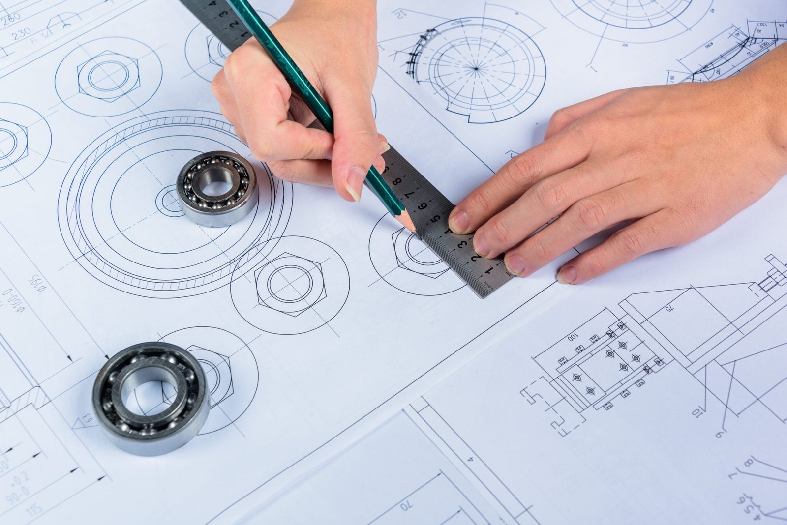
- AutoCAD for precise 2D drafting
- SolidWorks for parametric 3D modeling
- Fusion 360 for cloud-based design collaboration
- Creo and Siemens NX for advanced simulations
- KeyShot and Blender for high-quality renderings
These tools help us bring clarity, accuracy, and realism to our visualizations, making them ideal for both technical review and presentation purposes.
Our Visualization Process
At DesignHok, every machine component visualization project goes through a refined and systematic process:
1. Requirement Gathering
We begin by understanding the function of the part, material constraints, load-bearing requirements, and how the component interacts with other parts in the system.
2. Initial Sketching
Our design team creates rough 2D sketches or conceptual models that outline the key features of the component.
3. 3D Modeling
Using CAD tools, we build a precise 3D model. This step includes defining the exact dimensions, tolerances, and surface details.
4. Simulation & Validation
We simulate real-world conditions to ensure that the part will perform as expected. Stress analysis, thermal behavior, and motion analysis are conducted here.
5. Rendering & Visualization
We generate photorealistic renders or interactive 3D models that clients can review, rotate, and annotate.
6. Client Feedback & Finalization
Clients review the models and provide input. We make revisions if necessary and finalize the model for production or prototyping.
Key Benefits of Machine Component Visualization at DesignHok
✅ Improved Accuracy
Every component is modeled to scale, with accurate geometrical and dimensional details, reducing the chances of design flaws.
✅ Better Cost Control
Early detection of issues minimizes wasted materials, production errors, and costly design revisions.
✅ Enhanced Innovation
Designers can experiment with new materials, forms, and mechanisms virtually, encouraging creativity without financial risk.
✅ Faster Time to Market
Streamlined visualization processes lead to quicker design approvals, faster prototyping, and reduced lead times.
✅ Effective Team Collaboration
Multiple stakeholders—including engineers, manufacturers, and clients—can access and review the same model in real time, ensuring consistency.
Applications of Machine Component Visualization
Machine component visualization is used across several industries, such as:
- Automotive: Engine parts, transmission components, and suspension systems
- Aerospace: Turbine blades, structural brackets, and landing gear assemblies
- Industrial Equipment: Gearboxes, conveyor systems, and hydraulic components
- Medical Devices: Precision tools, implants, and robotic surgery parts
- Consumer Electronics: Housings, connectors, and internal mechanisms
Whether it’s a single bracket or a complex gear assembly, the ability to visualize components in detail transforms the way engineers design, test, and build mechanical products.
How DesignHok Makes a Difference
At DesignHok, we combine technical expertise with visual storytelling. We don’t just show you what a part looks like; we show you how it functions. We understand that each project is unique, so our solutions are always tailored, from basic 2D representations to advanced 3D simulations with animations and dynamic views.
Our team is made up of experienced mechanical engineers, industrial designers, and CAD specialists who are passionate about transforming ideas into reality. We serve clients across the globe, offering scalable solutions for startups, manufacturers, and R&D firms alike.
Final Thoughts
Machine component visualization is far more than just a design step—it’s a bridge between imagination and manufacturing. With DesignHok’s expertise and advanced tools, you can rest assured that your components are not only visualized accurately but also optimized for performance, cost, and manufacturability.
As engineering demands continue to evolve, so does our approach. Partner with DesignHok, and let us help you bring your mechanical concepts to life with precision and confidence.
FAQs
Q1: What software does DesignHok use for component visualization?
A: We use industry-leading tools like AutoCAD, SolidWorks, Fusion 360, KeyShot, and more for both 2D and 3D visualization.
Q2: Can you simulate the functionality of a component?
A: Yes, we can simulate mechanical behavior, stress, motion, and thermal performance using advanced tools to validate the design.
Q3: Do I need to provide sketches or ideas to get started?
A: While sketches help, they’re not mandatory. We can work from concept notes, functional descriptions, or even existing parts.
Q4: What industries benefit the most from machine component visualization?
A: Automotive, aerospace, medical devices, consumer electronics, and industrial machinery benefit greatly from this process.
Q5: How does visualization reduce manufacturing errors?
A: Visualization allows us to identify interferences, dimensional mismatches, and design flaws before any physical manufacturing occurs.