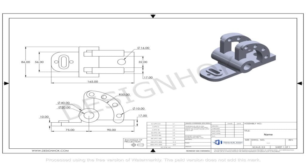
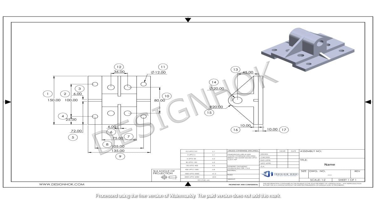
Description:
The essential steps and techniques involved in creating professional2D CAD Drawings A complete guide on setting up your drawing, choosing appropriate tools, and applying best practices to ensure accuracy and clarity in your designs. Whether you’re a beginner or looking to refine your skills, this guide provides the foundational knowledge to create detailed, effective 2D CAD Drawings.
Creating 2D CAD Drawings is an essential skill for engineers, architects, and designers. These digital drawings enable professionals to develop precise plans for products, buildings, or machinery. While the process may seem challenging at first, understanding the essential steps and techniques will help you build clean, effective, and professional drawings. Here’s a comprehensive guide to mastering 2D CAD Drawings

1. Understanding 2D CAD Drawings Basics
Before starting, it’s important to understand the fundamentals of 2D CAD (Computer-Aided Design) software. Most CAD programs, such as AutoCAD or DraftSight, offer similar tools and features, so once you understand the basics, you can apply this knowledge across multiple platforms. CAD allows for precise drawing creation, modification, and annotation, making it a powerful tool for developing technical designs.
Key Components of 2D CAD Drawings:
- Lines, Arcs, and Shapes: Basic entities that form the drawing.
- Layers: Layers separate various elements of a design, such as dimensions, annotations, and structure, which helps in organizing the drawing.
- Dimensions and Annotations: These provide measurements and notes to explain the drawing.
- Text: Used for labels and additional information.
2. Setting up Your Workspace
To start a 2D CAD Drawings, set up the workspace to ensure you have the correct parameters for your project.
- Choose the Right Units: Set the units to either inches, millimeters, or meters based on project requirements.
- Adjust Grid and Snap Settings: Grids and snap settings help you draw accurately by allowing elements to align precisely.
- Define Layers: Create layers for different elements of your drawing, such as dimensions, outlines, and annotations. Each layer can be color-coded for easy identification.
A well-organized workspace increases drawing accuracy and enhances productivity.
3. Begin the Drawing with Basic Shapes
Start by creating the basic outline of your drawing with simple shapes. The outline is the foundation for further detailing, so ensure it’s accurate.
- Lines and Arcs: These tools are fundamental in most CAD software. Use them to sketch your primary shapes, like rectangles, circles, or custom outlines.
- Precision with Coordinates: CAD software allows you to enter coordinates directly, ensuring accuracy. For instance, you can specify the exact start and endpoint of a line.
Take advantage of OSNAP (Object Snap) settings, which help you connect and align shapes easily by snapping to exact points like endpoints, midpoints, or center points.

4. Adding Detail with Tools and Commands
Once the basic outline is complete, add more details to make your drawing specific to the design requirements.
- Trim and Extend: Use these tools to adjust line lengths to meet other shapes or boundaries. They are especially useful for refining complex shapes.
- Fillet and Chamfer: These commands round or angle edges, which is often required in product and architectural drawings.
- Mirror and Rotate: If your drawing includes symmetrical elements, the mirror tool duplicates parts of the drawing on the opposite side, saving time.
- Array: For designs with repeated elements (like bolts in a mechanical design), the array tool lets you replicate parts efficiently.
The goal is to use these commands to make your drawing organized and accurate, ensuring elements are positioned correctly without manual adjustments.
5. Dimensioning and Annotation
Dimensioning is crucial in 2D CAD Drawings because it communicates the precise measurements needed for construction or manufacturing. Annotations provide extra notes for anyone interpreting the drawing.
- Add Dimensions: Use the dimensioning tool to add measurements. Options like linear, aligned, angular, and radius dimensions ensure that all types of measurements are covered.
- Insert Text: Annotations and notes explain specific details, such as material specifications or assembly instructions. Use the text tool to add descriptions where needed.
- Leaders and Arrows: These can point to specific areas in the drawing to highlight important details.
Organized dimensioning not only ensures clarity but also reduces misunderstandings during the production or building process.
6. Fine-Tuning with Layers and Colors
As you work, organize your drawing with layers and colors to make it visually clear and easy to interpret.
- Set Up Layers: Each layer can represent a specific part of the drawing. For example, use one layer for dimensions, another for main outlines, and one for auxiliary notes.
- Assign Colors: Assign colors to each layer to differentiate them. This makes it easier to identify parts at a glance, especially in complex drawings.
- Adjust Line Types and Weights: Alter line types and thicknesses to give your drawing more detail. For instance, use dashed lines for hidden elements and thicker lines for main structures.
Layers help keep a CAD drawing organized, which is especially beneficial when sharing the file with others who may need to edit or view specific parts of the design.
7. Quality Check and Final Adjustments
After completing your drawing, go through a quality check to ensure accuracy and clarity.
- Use the Check Dimension Tool: This tool verifies that all dimensions are consistent and within tolerance.
- Examine Overlaps and Gaps: Ensure that no lines overlap incorrectly and that all shapes connect as intended.
- Spell Check for Annotations: Minor errors in text can cause misunderstandings. Use the spell check tool to review text annotations.
Quality control ensures your drawing is error-free and meets the standards necessary for production or further design stages.
8. Saving and Exporting
Finally, save your drawing in the appropriate formats. CAD drawings are typically saved as DWG files, but many clients or collaborators may require PDFs for easy sharing or printing.
- Save in Multiple Formats: Save a version in the native CAD format (DWG or DXF) and export a PDF for easy viewing.
- Organize Files with Descriptive Names: This ensures that each drawing is easy to locate and identify, which is essential when dealing with multiple files in a project.


